Requirements:
For the CNC Router foam Maze assignment there were certain criteria that I had to follow.
- Create a maze no bigger than 8.5x11 inches. These mazes can be any shape as long as it fits on the dimensions given.
- Use Inventor to create a 3D maze. These mazes should have a 3/8 inch border around the perimeter and have 5/16 inch wide, 1/4 inch deep channels for the ball to travel. The material will be ¾ inch thick foam to start. There must be a definite start location and finish location.
- You will use the CNC router to cut out the entire maze including channels, start/finish and perimeter.
How I created my foam maze
Day 1
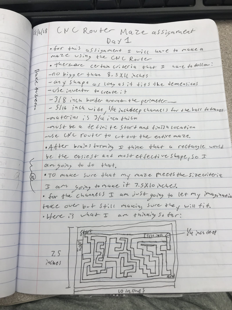
I started out the day familiarizing myself with the criteria so that I knew I would follow them. I then brainstormed which shape I wanted to use. I decided that a rectangle would be the would be the easiest and most effective shape to create my foam maze out of. To make sure that I didn't go over the size requirements I made my maze 7.5X10 instead of the maximum it could be which is 8.5X11. For the channels I was going to make sure that they were the right size but I wasn't going to have a specific pattern for them, I would sort of let my imagination take over here. I was able to sketch out my plan in my designer notebook and started working on it in Inventor. However creating the maze in Inventor was a lot harder than I had originally planned, especially the channels.
Day 2
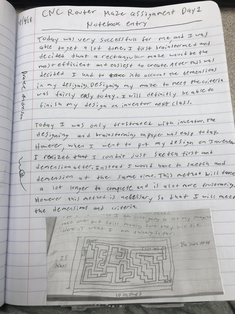
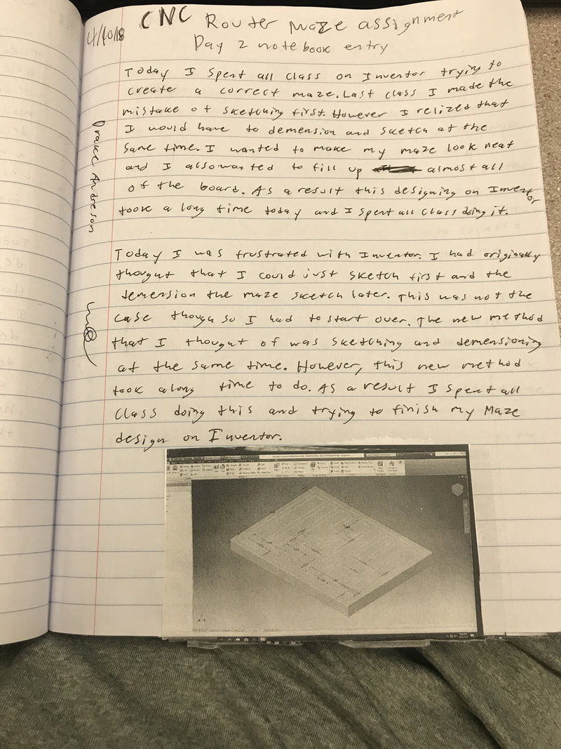
Today was pretty frustrating. Last class I sketched out my maze in my notebook and started creating it on Inventor. I wanted the maze to look neat and I also wanted to fill up almost all of the foam maze. However this proved a lot harder than I thought. I originally thought that I could just sketch my lines and then dimension them later but I realized that I would have to sketch and dimension at the same time. Because of this I spent all day on Inventor trying to make sure all the channels were the correct size and that they were where I wanted them.
Day 3
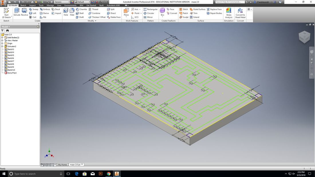
Today I had anticipated on finishing designing my maze, however this was not exactly the case. Last class I had finished sketching and dimensioning my maze in Inventor and my channels finally looked how I wanted them. So this class all I had to do was extrude those channels. For some reason though the channels wouldn't extrude. I quickly realized that it was because one of my channels was not closed so I couldn't extrude it. Instead of spending an entire class looking for the source of the problem I decided that it would be faster and easier to start over, even though this was already my second try. This decision proved to be very helpful, as I was able to create a working maze design in Inventor in half the time of the one before and this one I could actually extrude. At the end of the day I would view today as a win, even though I had to start over for a second time, I was finally able to create a successful Maze design on Inventor.

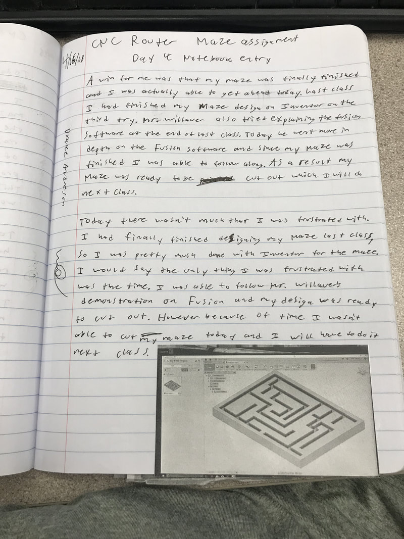
Day 4
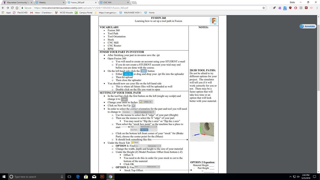
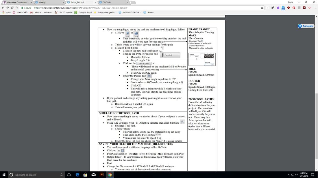
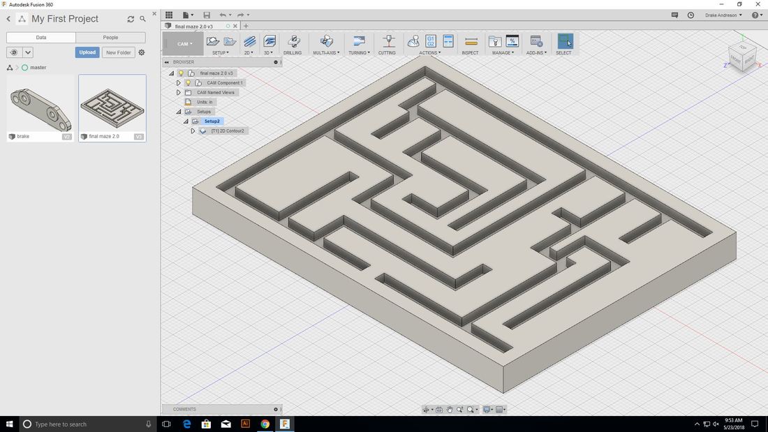
Today was a big win for me, I guess third time is the charm. Since I had finally finished my maze design in Inventor last class on my third try, I was ready to follow along with Mr. Willauers instructions on moving it over into Fusion 360. (In order to cut out our design with the Router or mill we have to convert our file into Fusion, we cant do it from Inventor). I was able to follow along with my own file as Mr. Willauer demonstrated what to do on the projector. I I first downloaded my Inventor file into Fusion 360. After that was done and I had selected my file I made sure it was in CAM and also that the measurements were in inches. Next I hit new setup and made sure that the brake was oriented correctly with the X, Y, and Z axis's, by clicking on the middle point. After that I made the dimensions the size of my material. Next I hit 2-D contour and then hit the geometry tab and selected the bottom of walls. After that I would have to make a new tool bit. I chose the flat end mill drill bit, made the diameter 0.25 in and the body length 2 in. Since I was able to follow along with Mr. Willauer on getting my maze all set up to cut out, I will be able to actually cut out my maze next class. I then clicked on the feed and speed tab and set the spindle speed to 10000rpm, and the Cutting Feed Rate to 200. I then hit the Passes Tab and changed the Max rough step down to .25”, and Stock to leave to 0. Next I ran my simulation. After that was completed successfully I clicked on the G-code button, selected Forest Scientific, and saved it to my flash drive.
Day 5
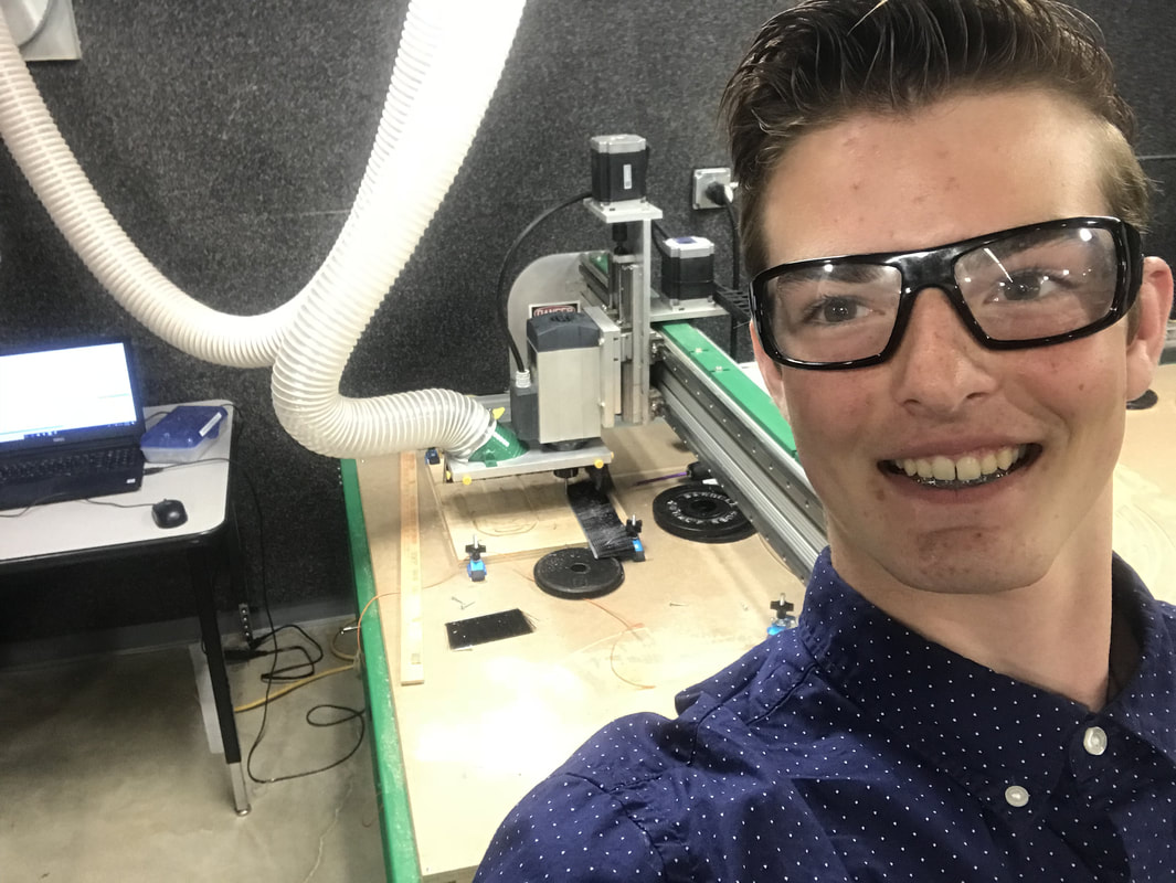
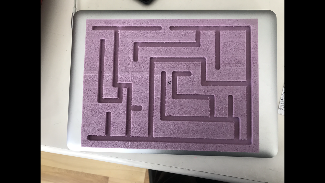
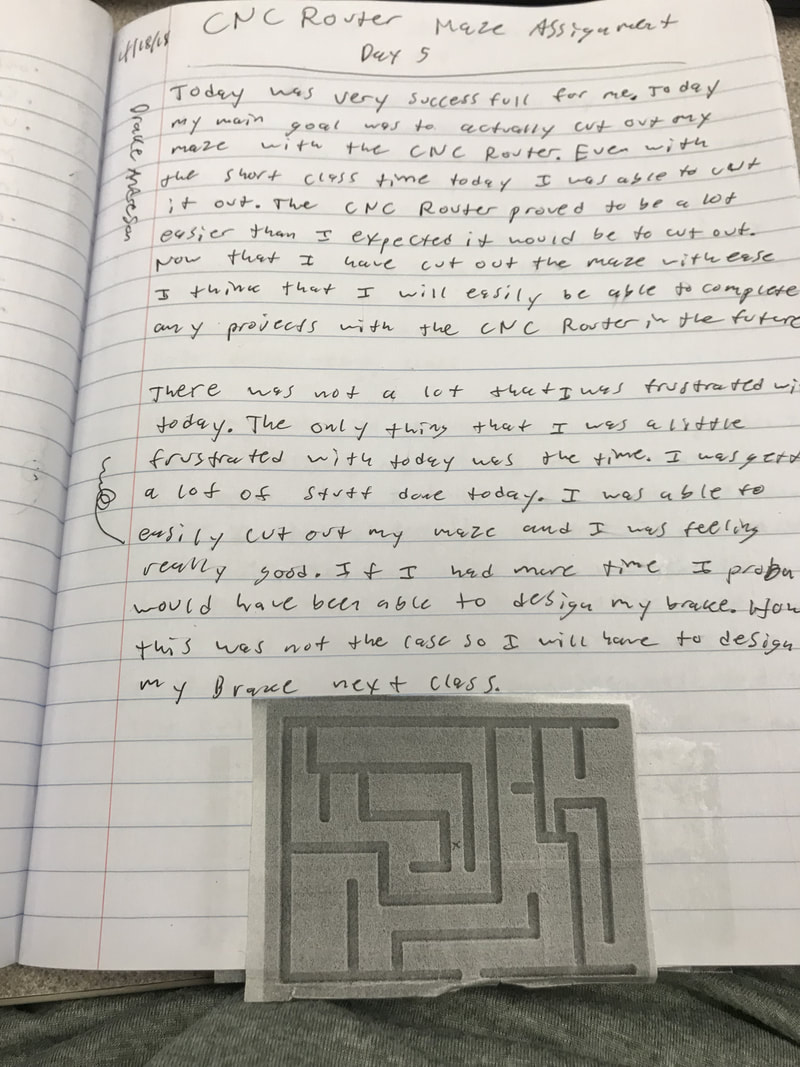
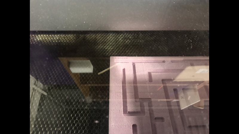
Today was a very successful day and I got a lot accomplished. Today my major goal was to actually cut out my maze with the CNC Router. Even though the class time was short today I was able to accomplish my goal. I first started by grabbing the correct size foam and then put double sided tape on the bottom of the foam piece. After the double sided tape was on I stuck the foam onto the CNC Router machine. The CNC Router actually proved to be a lot easier than I expected it to be to use. I first loaded my file on to the computer hooked up to the router. Next I moved the drill bit to the center of my foam that I had measured out earlier. I then grabbed this metal box and placed it on the middle. What this box does is I am able to click a button and the drill bit goes down to the metal box and senses how high the material is. After this I could run my maze file making sure that my hand was on the space bar. The CNC router ran without a problem and my maze was finished cutting out by the end of class. Now all I had to do was laser engrave my name and hour which I was going to do after I did my brake part on the CNC mill.
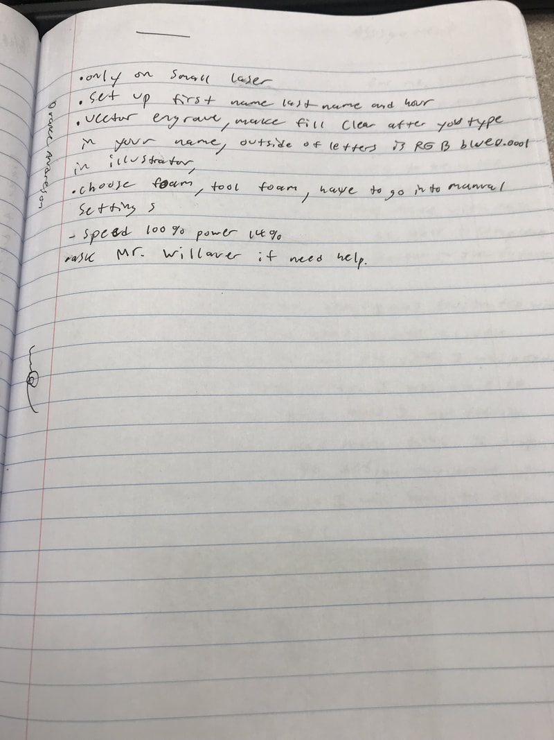
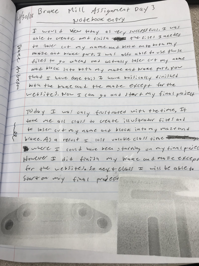
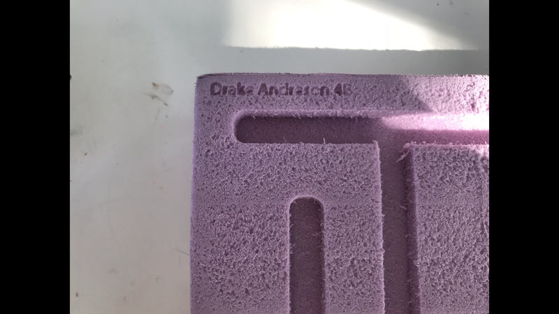
Laser engraving my name
After I had cut out my maze on Day 5 I moved on to the brake part and the CNC mill. After I had finished the Brake part and had cut it out I laser engraved my name and hour into both the maze and the brake part. I first had to make an illustrator file for this. I made the art board the same size as my maze (7.5X10). I then created a text box and typed in my name and hour. Next I made sure that the text was no bigger than 3/8 of an inch because that how big the border around the maze was, and that was where I was going to engrave my name and hour. Next I made outlines on my text, made the stroke weight 0.0001, and changed the border color to RGB Blue leaving the inside of the letters clear. After this was done I saved the file onto my flash drive and went down to the laser. Under setup and preferences I chose tool foam, and also made the speed 100% and power 14%. After this I laser engraved my Maze. After I had done this my CNC Router maze was complete.

Online Files
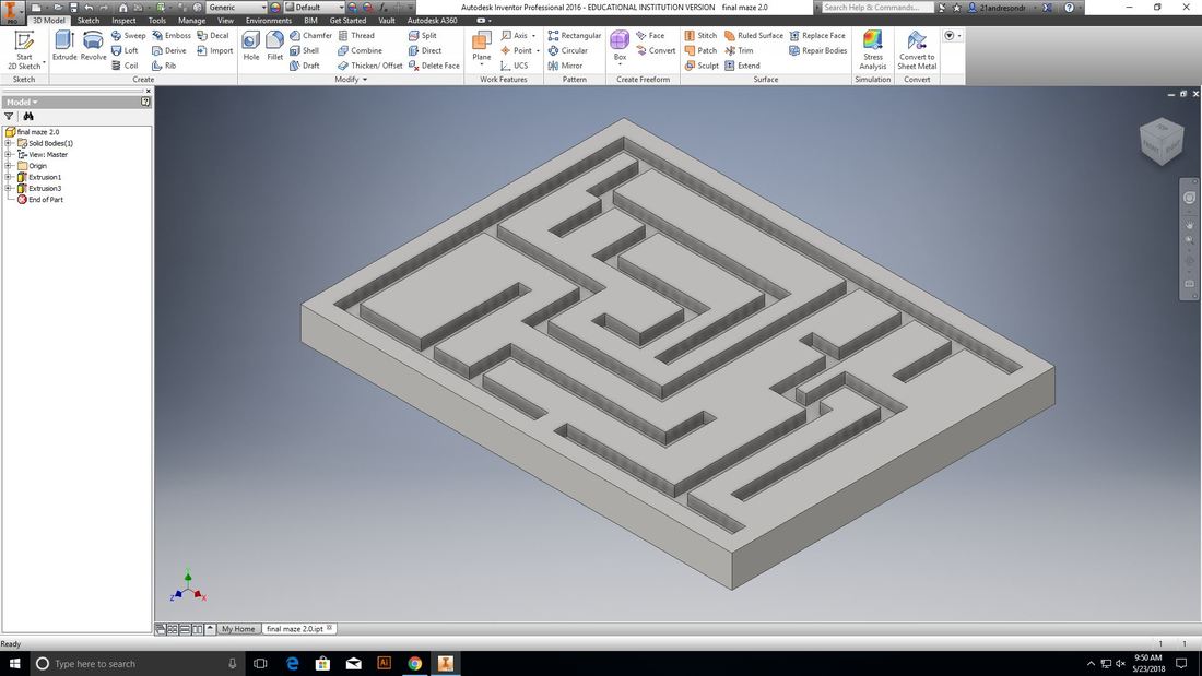
Here is my Maze file that I created on Inventor;
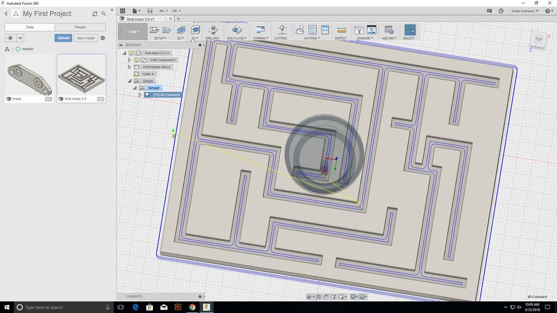
Here is the Maze file moved into Fusion 360;

Here is the tool path for my maze on Inventor;
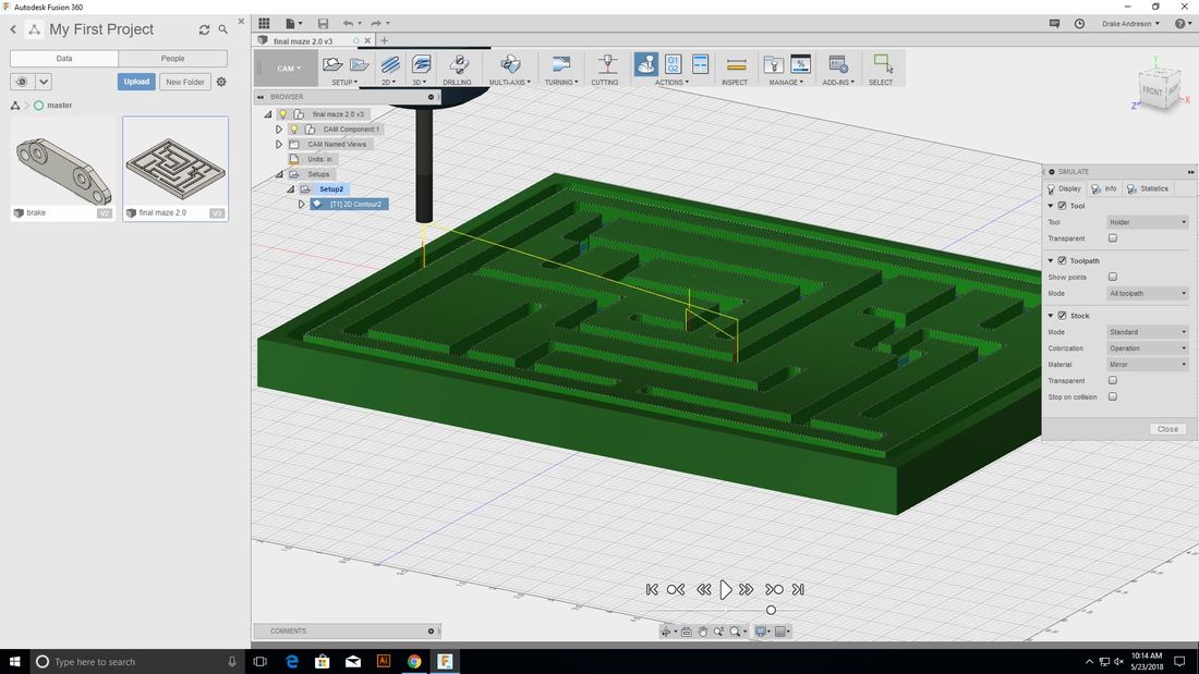
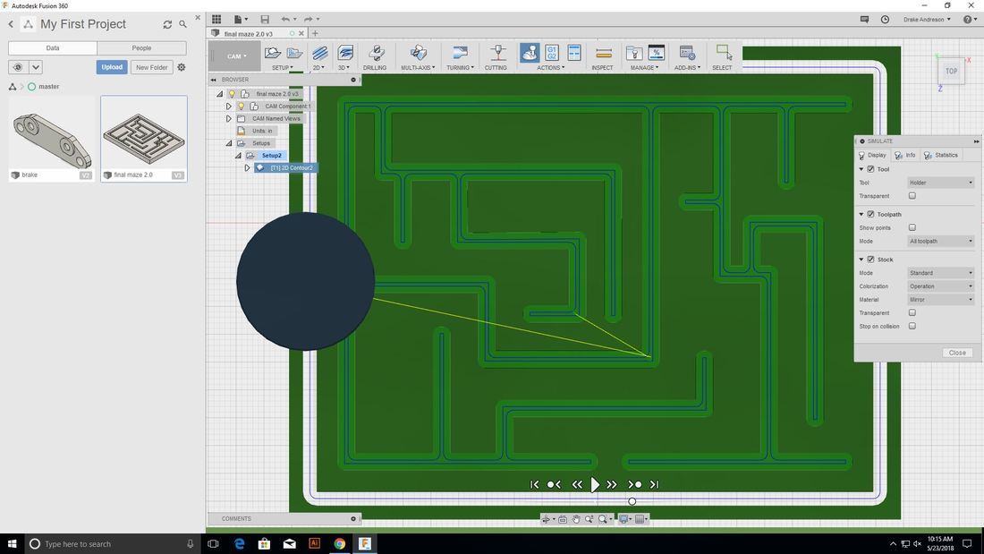
Here is the successful simulation on Fusion 360);
My Illustrator file to laser engrave my name into my maze;
What I learned
This taught me a lot not just about the CNC Router Machine but also the different software that goes along with the CNC Router. By creating the maze on Inventor I had to use many different tools and options that I would have never used before. So as a result creating the maze on Inventor introduced me to new things on Inventor and made me even more comfortable using Inventor. This CNC Router rotation also introduced me to fusion 360 for the first time. Unlike Inventor I had actually never used Fusion 360 before. This CNC Router rotation both introduced me and taught me how to use Fusion 360. This would prove very helpful in the future because I would also have to use Fusion for my brake part and anything in the future that I would have to use either the CNC Router or Mill. I also learned how to use the actual CNC Router Machine. I originally thought that it would be really difficult to use but after Mr. Willauer showed me how to use it I would now be very comfortable with using it in the future. And finally I learned some valuable life lessons like not giving up. It took me three tries to finally create a working file on Inventor and I could have easily gave up many times but I didn't give up and I succeeded in the end.
