Requirements:
For the Foam Brake part there was certain things that I had to do and follow
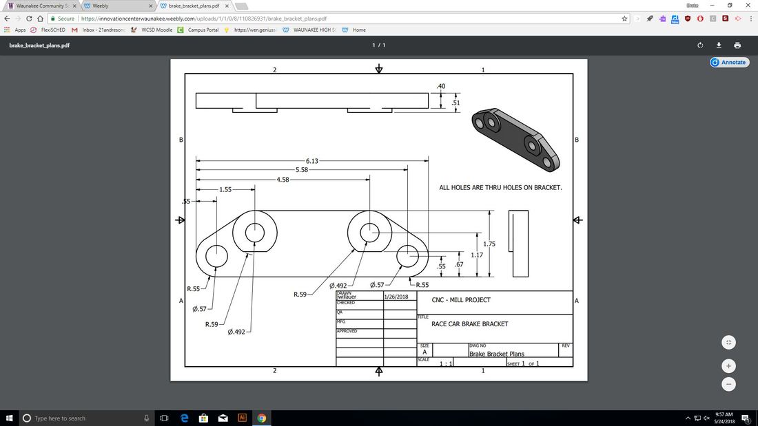
- Draw the part “Brake Bracket” using Inventor and upload to Fusion 360
- Use Fusion 360 to generate tool paths and G-code to cut out this part. You will be required to use two different processes and tools to complete this part.
- Use the CNC Mill to complete a mock-up of the Brake Bracket out of blue/pink foam
How I created my foam brake part
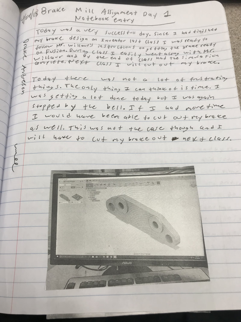
Day 1
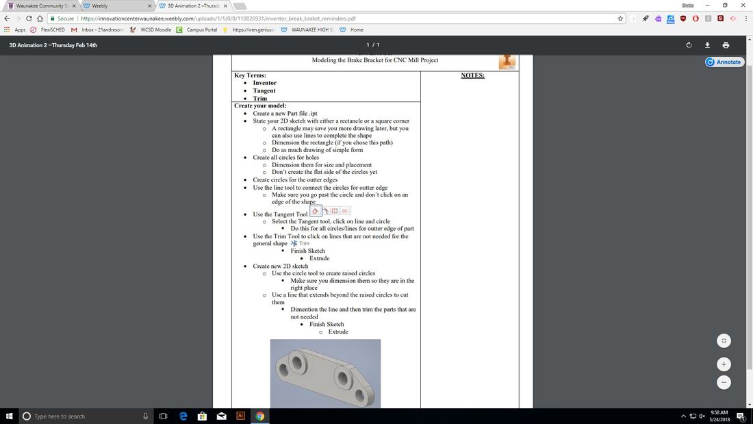
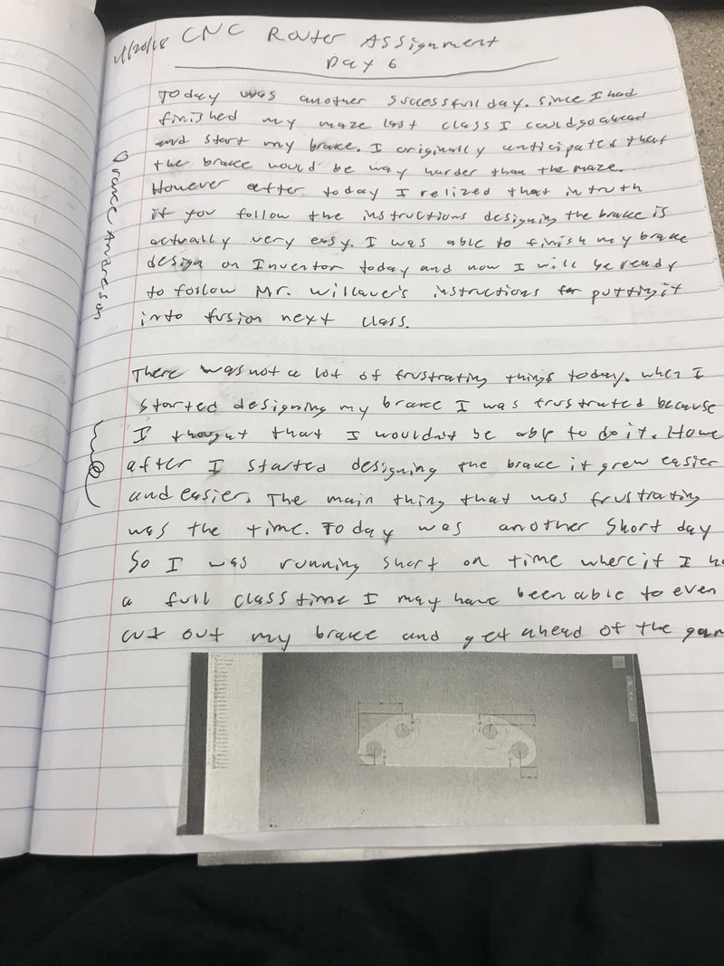
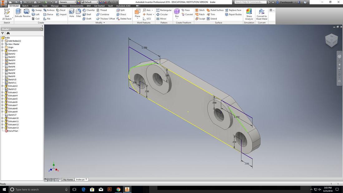
Today I started on my Brake part. We were given a sheet with the dimensions of the brake part to make sure that it was the right size. Using the sheet with the dimensions, as well as prior experience using Inventor, and the Inventor brake handout, I began to create my brake part. I originally had thought that the brake part would be very hard to create. However as I began creating it and following along with the instructions I realized that it was actually way easier to make then I had originally thought. I began by creating a rectangle with the dimensions on the dimension sheet. I then made sketches using circles and line tools, and then extruded them on the rectangle to create the brake part shape. After that I made other circles and extruded them to make the holes and circles on the brake part. Throughout this process I used the sheet with the dimensions to make sure that my brake was the right size. By the end of class I had finished my brake part. As a result I would be ready next class to follow along as Mr. Willauer showed us how to set up our brake part on Fusion 360.
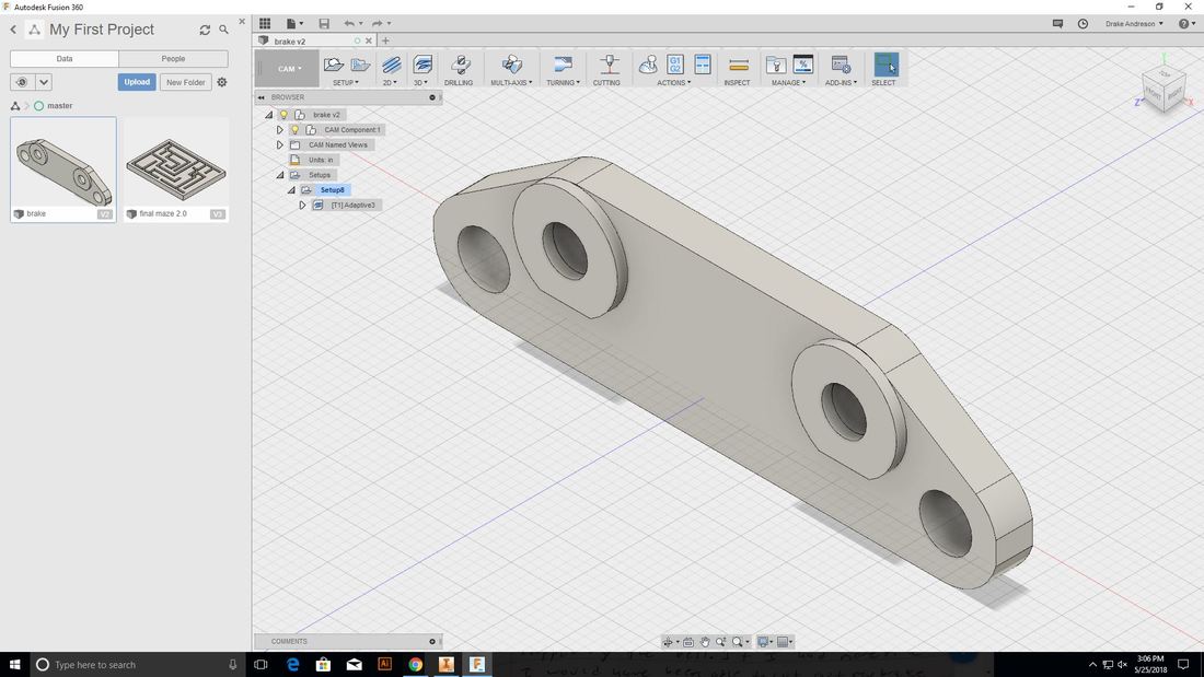
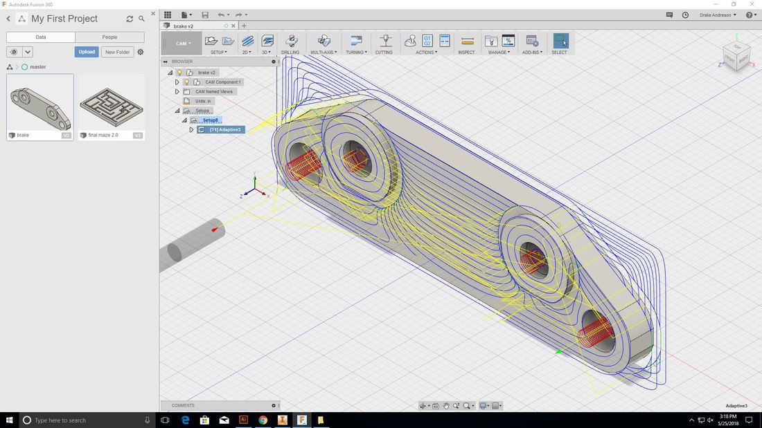
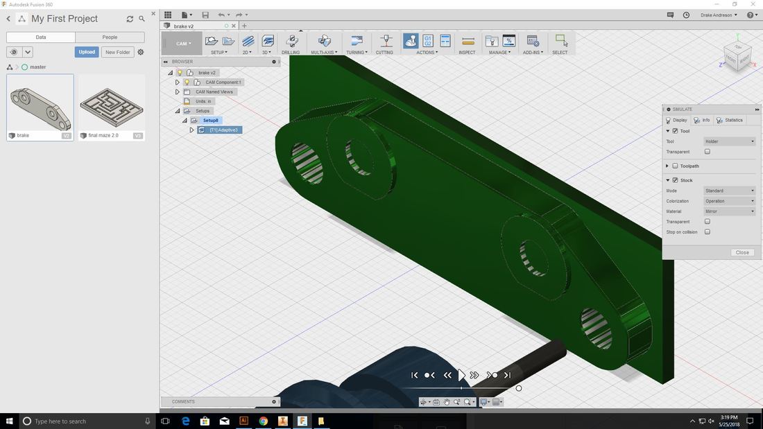
Day 2
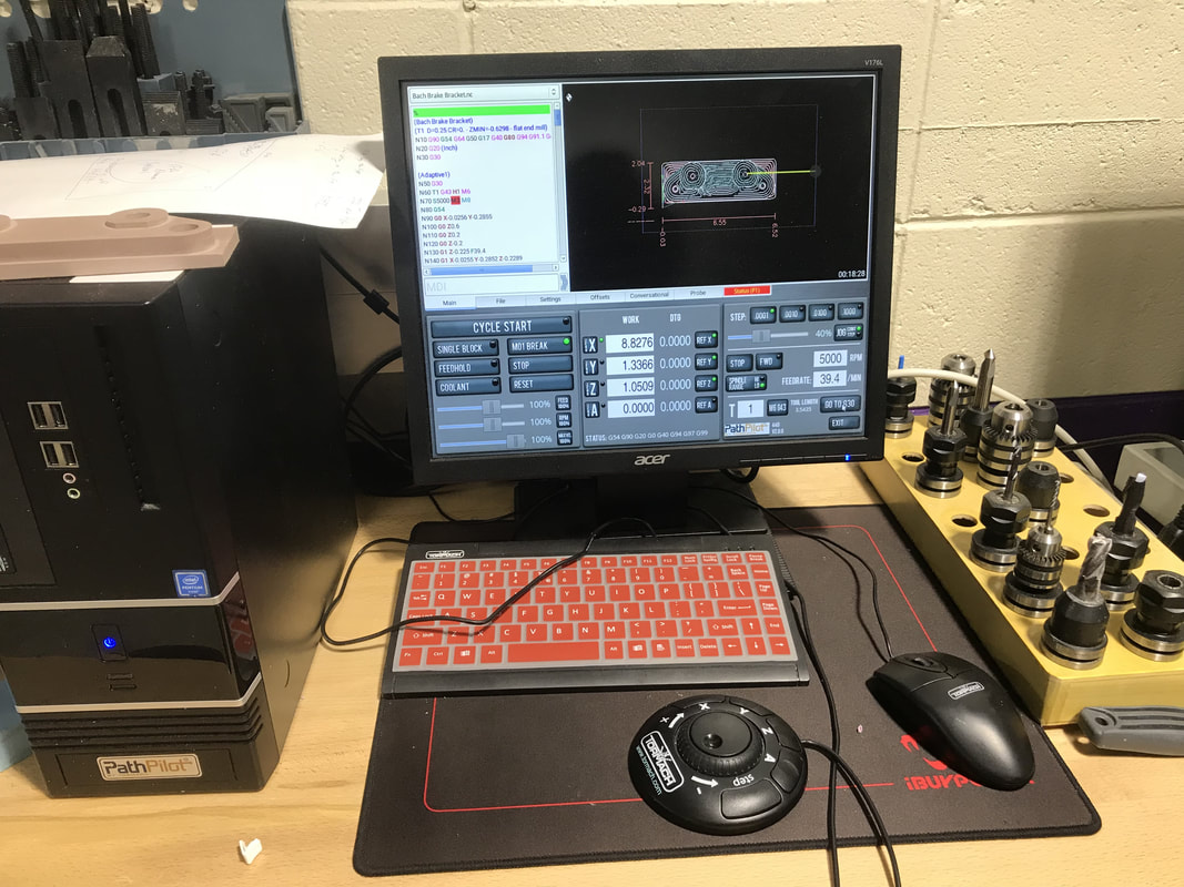
Today was again a very successful day for me. Since I had finished my brake drawing on Inventor last class I was ready to follow along this class. Bringing the Inventor file into Fusion 360 was fairly easy and similar to the Maze that I just did, all I had to do was upload it from Inventor. After that was done and I had selected my file I made sure it was in CAM and also that the measurements were in inches. Next I hit new setup and made sure that the brake was oriented correctly with the X, Y, and Z axis's. After that I made the dimensions the size of my material. Next I hit 3-D adaptive clearing and then set up my tool, which was easy because I could use the one that I had already made from the maze. Next I selected the Feed and Speed tab and then changed the spindle speed to 5000rpm. Then under the passes tab I changed the Max rough step down to 0.25 and stock to leave 0. I then hit OK and waited while it generated a tool path. After the tool path was generated I could simulate the cutting out. To save the file I had to generate G code, I chose the G1 G2 label and selected Tormach path pilot. I then saved it to my flash drive. There wasn't enough time to start cutting but I was very happy that I was now ready to cut, and could do that next class.
Day 3
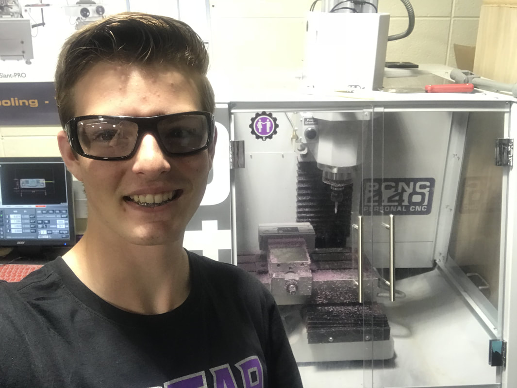
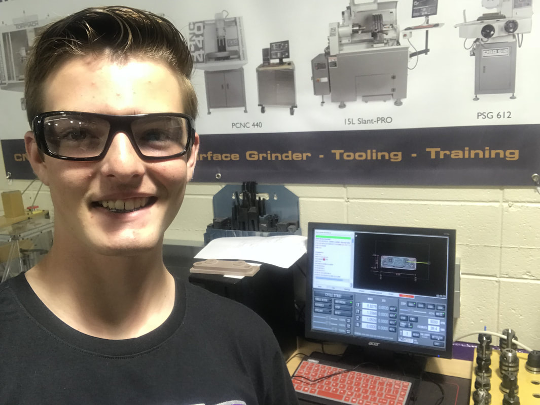
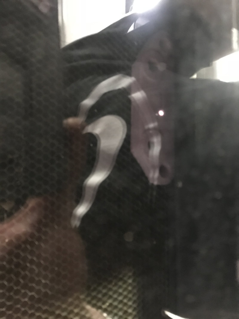
Since I had got my Brake part file moved to Fusion 360 last class and had gotten it ready I could go ahead and get it cut out today, with the CNC mill. Most of class I had to wait my turn to use the CNC mill because other people were using it. However before the end of class I was able to get on the CNC mill. I opened my file on the computer connected to the CNC mill. Next I moved the drill bit to the corner of my file. I also grabbed a paper and slid it back and forth under my drill bit and kept moving the drill bit down until I couldn't slide the paper back and forth anymore. After this i made the X, Y, and Z axis's zero. Finally, making sure that my finger was on the space bar I ran my brake file. I was able to get it successfully cut out today which was a big win.
Day 4
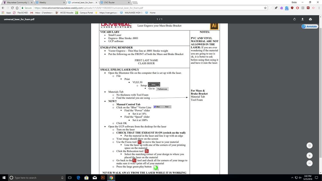
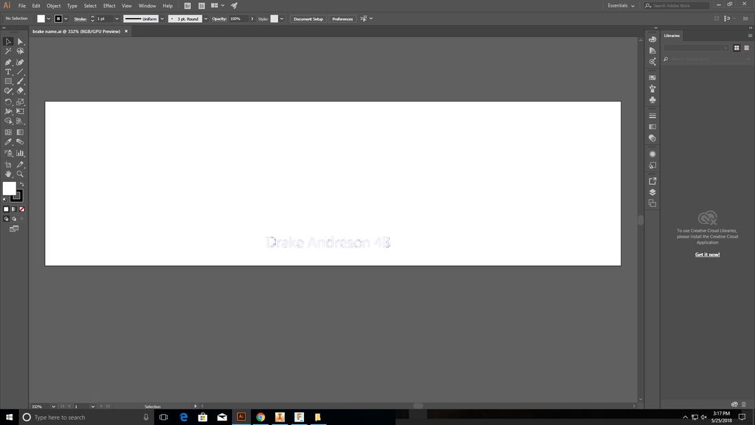
Today since I had finished cutting out my brake part all I had to do was laser engrave my name and hour. I went on to Illustrator and made an artboard the same size of my brake part. Then I made a text box and typed my name and hour into it. Then I moved the text into the middle of my artboard. I then made outlines on my text and made the stroke weight 0.0001. I also changed the outline of the letters to RGB blue and made the inside clear. After this was done I saved the file onto my flash drive and went down to the laser. Under setup and preferences I chose tool foam, and also made the speed 100% and power 14%. After this I laser engraved my brake. After I had done this my CNC mill brake part was complete.
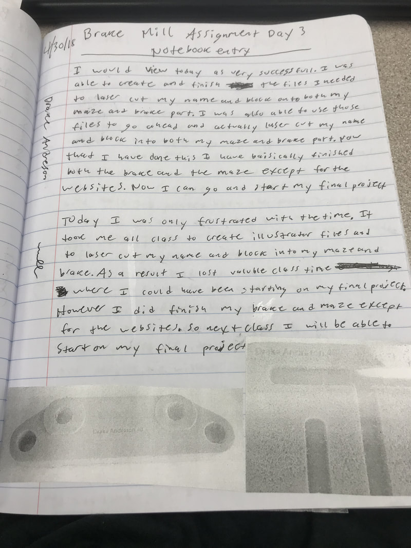
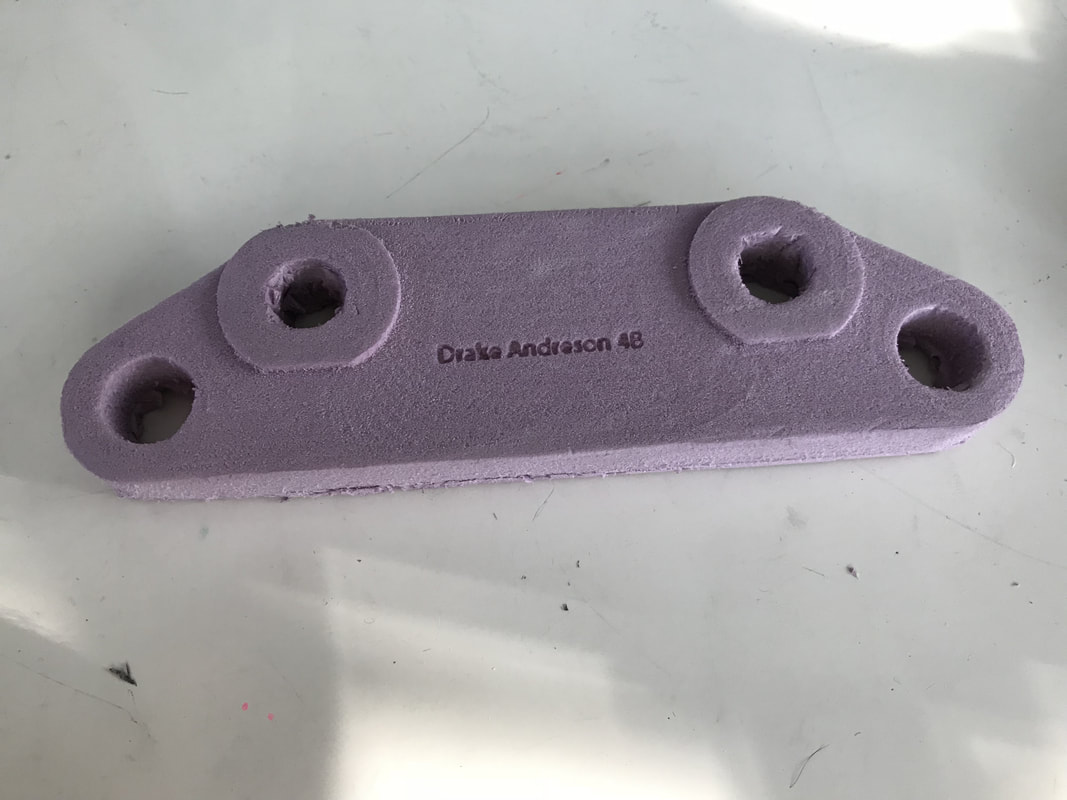
Final product
Here is my finished product;
What I learned
This CNC mill assignment was very helpful for me. I not only learned how to use the CNC mill, but I also grew more skilled with Inventor and Fusion 360. Before this assignment I probably would not have even thought of making something as complicated as a brake part. However even though I originally thought creating the maze would be really hard I was able to easily create it on Inventor and grew more comfortable using Inventor. Last rotation with the CNC Router I was first introduced to Fusion 360 and after this rotation I was more than comfortable with using Fusion 360. Finally I was also introduced to the CNC mill for the first time. Before using it I had no idea how to use the CNC mill. However afterwards I now feel comfortable using the CNC mill for any projects in the future. As you can see between learning a new machine and familiarizing myself with software I learned a lot during this CNC mill rotation.
